
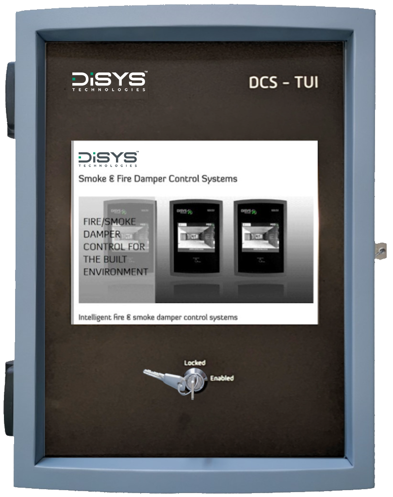
The DCS TUI Damper Control Panel adds an innovative touch screen user interface to the Disys damper control system. This allows for cost effective customisation of the user interface in order to provide multiple fireman’s overrides as required.
- Monitor and control of up to 2000 dampers (via the use of LNI)
- Directly interface to fire alarm panels
- Up to 200 zones
- Touch screen user interface
- Each device (most commonly a fire/smoke damper) on the network needs a Disys controller interface node in order to communicate with the panel. For more information on how our damper control panels work, see our product selection guide.
Status & Control: Via the intuitive touch screen interface the user can view the status of all dampers on the system, testing can be performed by loop or by zone.
Network Optimisation: By networking any of our DCS damper control panels, the best, lowest cost solution can be achieved as dictated by the layout of the building.
Inter Panel Network: Prioritised messaging ensures that alarm messages are relayed as a priority between panels.
Customisable graphics: Simple outline zone/building drawings may be created and dampers status icons placed on them.
Large Network Capability: Individual panels are located anywhere on a communications loop of up to 3 kilometres in length.
Battery Backup: EN54-4 Compliant 2.3Ah internal battery. Hold up time of 2 hours.
BACnet: Add a BACnet BMS interface
Dimensions (WxHxD): 325.5mm x 410mm x 154mm
Connections: Cable gland knockouts on top side, gland plate on bottom
Doors: Left as standard (Can be on right by request)
Material: Powder coated mild Steel
Weight: ~8 Kg
Electrical
Supply: 90-264 VAC ; 47-63 Hz., 300W
Supply Wire Size: 1.3 – 2.5 mm² / AWG 16 – 14
Power consumption: 45W (max)
PSU approvals: EN 60950-1
Optional Battery Backup EN54-4 compliant 2.3Ah internal battery. Hold up time 2 hrs.
Fusing: Internal 1A a/s 20mm
Digital Inputs: 5V 10mA to volt free contacts, 4 off fitted as standard, 1 additional used for psu fail detect
When battery backed supply option selected.
Digital Outputs: 1 Opto-isolated 24V 100mA rated
– common fault signal normally
closed, open on fault.
Additional Interfaces:

LNI
The LNI or Loop Network Integrator is designed to allow multiple loops (each loop restricted to 125 devices) to communicate over a master loop to the TUI control panel. This increases the amount of devices that can be connected to the TUI whilst maintaining communication speed and reliability.
Datasheet: LNI (Loop Network Integrator)